EccentricGenius

Stopping Time (Visually)

UNDER CONSTRUCTION…

Recently, Nate True of Cre.ations.net posted a very nice project involving some water, some electronics to provide the illusion of time distortion. (Time fountain)

I have been long since interested in high-speed photography. Many years ago I built a very simple device using some aluminium foil, an air rifle, a couple of ligth triggered Flash units and, of course, a camera.

The basic concept is this: You are in a dark room. If you synchronize a flash of light with the occurance of an event, you will see that event "suspended" in time without th need of highspeed photographic equipment.

In the case of the Time Fountain, as Nate likes to call it, it has been always an interesting and fun phenomenon to watch at museums, or at home if you own a strobe light.

FrozenTime-small.jpgWe start with a water stream or constant rate. Imagine we are able to detect drops of water falling, and we trigger a flash of light slightly after each drop is detected. If the drops are coming at a fast enough rate, we will see a shining drop of water suspended in mid air, in an otherwise dark area. We are obviously not seeing the same drop of water, but different drops of water that are "caught" by the flash of light at exactly the same position each time, giving the illusion that it is the same dropplet. Because we are triggering the flash events with the dropplets, the flash rate T_f is equal to the dripping rate T_d, i.e., both will coincide at every time step.SlowMo-small.jpg

Now, if we want to give the impression of time moving forward but in slow motion, all we have to do is record the time between drops and slightly increase it by a time delay \delta t for each consecutive drop. The time between flashes is then T_f=n(1+\Delta t), where n is each time step. That way each flash of light will show a droplet at a position slightly further down the path, giving the illusion of it falling down at slow rate.

Nate has done this using a trigger mechanism based on an OP AMP comparator circuit and an PIC microcontroller to provide the flash timing. Simply flashing the light in synch with the dripping water will "stop" time. And by altering the pulse frequency linearly (ramp like) will create the slowmotion, or even backward motion effects.

There is a shortcut.

Option #1
Start with a constant water dripping stream. Then blink really really fast. Ok, just kidding (or maybe not).

Option #2

Since we are not after the precise location of a given dropplet of water in space, we can forego the synchronization mechanism and just flash the light (LEDS in this case) at a constant rate. It doesn’t matter where in space we catch the dropplet, as long as we catch it consistently.

Stream-small.jpgIf the dripping rate is a multiple of the flashing rate, the flash of light will catch the droplets at the same position each time.

But what about slowmotion and backwards motion? Well it’s easy as too.

Imagine the drop rate is the same as the flash rate. Now we make the flash rate slightly slower, in other words we increase the time between flashes just a little bit: T_f=T_d+\delta t. The first drop will be caught at a certain point, but the next drop will be caught a point further down because we had some time left over from the previous flash. By adjusting the delay we can effectively change the rate of apparent fall. If the time between pulses is shortened we will catch the droplet at a higher position each time, giving the illusion of it moving backwards in time.

We have limited the discussion to a single flash of light during the whole length of the falling trajectory, but in practice, due to the periodic nature of the experiment, we will see at least two droplets of water along the path if we adjust the flash frequency to something other than the dripping rate. Usually the time it takes for a dropplet to fall all the way down is much larger than the time between drops, therefore we will see several dropplets suspended in mid air along the stream.

Now, how do we do this for real?

The circuit

The simplest way to provide a series of pluses where we can control both the pulse duration and the frequency independently of each other: a 555 Timer chip and some LEDs.

Streak-small.jpgThe 555 circuit is used in an astable oscillator configuration but in an non-obvious way. If we just go ahead and build a traditional 555 oscilator circuit and try to adjust the frequency of the pulses, we will find that we will be adjusting the pulse width as well. If the pulse width, or pulse duration, is too long, instead of seeing a single droplet, we will see a streak of water, which is not very interesting since it is very similar to the way we are used to experience water streams.

Instead, we hook up the LEDs to the output and the +V so that we can fix the pulse width to a very short duration, and use the other resistor in the circuit to vary the frequency. Because the LEDs is ON for such a short period of time, we don’t even need a current limiting resistor, but I will leave that as optional in case you think you may burn out your LEDs (they do not burn for me, but do a test with 1 LED first).

Here is a version of the circuit which I have used and tested. You may want to add a transistor buffer at the output in case you have lots of LEDs. I tried 4 super bright white LEDs and they work fine without the need for a transistor buffer.

555Strobe-small.jpg

Lighting considerations

Shining light on transparent water has its own subtleties. Nate solved this by the use of UV LEDs and fluorecein, and it works fantastic. Luckily I had some fluorescent green dye stored in my lab. But there are other options.

Vegetable dye (food coloring dyes) work well, so does koolaid. These won’t need UV LEDS. Milk on a black background gives fantastic results and it is my favorite so far. Milk is organic so it will spoil and the smell won’t leave you any motivation for playing with the fountain. So we either innoculate cows with preservatives, or we can use certain varnishes and resins that look white when mixed with water. Whiteout or white paint is another option, we just need to make sure we add plenty of water to it so that it doesn’t clog the system.

If the liquid we use is semi-transparent the best lighting may probably come from either the side or the back, as can be appreciated in those gorgeous glassware product shots we are acustomed to seeing.

Frontal illumination at 45° from each side is probably the dullest (it’s the no shadow scheme used in TV studios).

Once I have some photos (tonight) I will post what the effect looks like. Also I have an idea for a simple rig with no motors needed.

The Drip Source

ContainerTop-small.jpgThe best solution is possibly the use of a small fountain pump and some tubing. But if you want to make some quick tests, a simpler device may be used.

A container with a hole won’t work because the dripping will be very chaotic since the water will adhere to the walls of the container in an unpredictable way. This is easily fixed by gluing a piece of aquarium tubing to the container wall.

ContainerSide-small.jpgThe best container is one that has a large surface area so that the water level changes slowly enough to be able to synch to the dripping rate. A bottle will not work as well. Also, the hole is better placed on the side wall (vertical wall) instead of on the bottom, and the tubing works best if held somewhat horizontal.

The hole in the container will need to be adjusted until the drip rate is fast but not too fast, so that the drops can be easily separated by the light flashes. I started with a small hole and expanded it with the tip of a pen until I got a good rate.

Published in: Artistica, Empirica, Scientia | on August 10th, 2006 | 83 Comments »

Bipolar Binaural Galvanic Vestibular Stimulation

or how I learned to control humans with electricity

MastoidProcess-small.jpgThe effects of Galvanic Vestibular stimulation have been known for quite a while. But it was not until recent years that the phenomenon has picked up quite some interest in the scientific community and the public eye.

I read the papers, saw some videos from japanese researchers, and thought to myself… this can’t be that hard. And it wasn’t.

So I took a 9V battery, a pair of electrodes (the same I had made for my GSR-Lie Detector) stuck them to my Mastoid Processes (the conic bones that end behind the earlobes) and presto. In no time I was leaning to one side or the other as my vestibular system was affected by the galvanic current.BellonBBGVS-small.jpg

Once I was convinced it worked, I designed a circuit to be able to regulate the current (to about 2-3mAmps) and a 4 switching transistor system for easy polarity reversal.

I ended up with a box with left and right buttons and a dial for adjusting the current (via a 10KOhm Pot). Looks sort of like a nintendo controller. Perhaps in the future I will build the first video game console where you will be able to play Mario Bros. WITH your parents, instead of a tv screen.

Schematic-small.jpg

Here is the schematic. To set the inputs to high you can just hook a couple switch buttons (like the ones I used) to the 9V battery. Pressing a button will set that input to high, and thus bias the corresponding transistors. Pressing the other button will reverse the polarity. The variable resistor is a potentiometer, a 10K worked fine for me.

WARNING! Applying electricity to your head is not a good idea. Don’t do it. You have to be nuts to even consider it.

So in essence, if the subject closes his eyes (or her eyes; I do not discriminate among my victims), the subject will lean towards one side or towards the other. If made to walk, this effectively makes the person go in a given direction under the control of the experimenter. As an added bonus, it has come to my attention, after several subjects mentioned it, that the application of the galvanic current generates a pleasurable sensation. Upon further research it seems that the current is stimulating pleasure centers in the nervous system. This of course is worth more investigation!

Published in: Empirica, Mad Science, Mind Warp, Scientia | on May 17th, 2006 | 23 Comments »

Tri-Field Meter

I finished the EMF and the Electric Charge sensors of my tri-field meter.


FieldMeter2-thumb.jpg I am still missing the Magnetic Field sensor, but that will have to wait until I have some time to test the Hall Effect sensors and figure out which one is more useful.


At this point the meter has extremely good sensitivity to charge when the antenna is fully extended.
Also, the EMF sensitivity can be toggled between 20x to 200x. The output signal is displayed by two blinking LEDs and heard though an internal speaker that can be turned on or off. The signal can also be fed into a voltmeter, oscilloscope or any other data acquisition system via the external plug on the bottom of the unit.


I also added a floating and fixed ground toggle. Fixed ground picks up high current signals, and floating ground is fantastic for sensing the tiniest signals like that of a quartz watch.


The EMF probe is a telephone pickup coil, and the charge probe is just a telescopic antenna.


I will post the schematics when I have time.


It is much fun listening to EMF activity around the house. Talk about pollution! It’s just amazing how much radiation is around us.

Published in: Empirica, Mad Science, Scientia | on February 17th, 2006 | No Comments »

Shallow depth-of-field on video (part 2)

Building a 35mm DOF adapter

The task of making a usable 35mm DOF adapter is simple yet contrived. The actual crafting offers little challenge, it is the design and the selection of appropriate components that makes it both interesting and complex.

After reading all I could find on this topic I realised that this is a type of device that has not matured enough yet to be offered to the consumer at an affordable price. It either is attainable at really high prices (several thousand USD) or at a lower price (sub 1000 USD) but built by enthusiasts; something which is by no means a bad thing.

Because of the state of the market for this type of product there are uncountable attempts by do-it-youself adventurers that will try just about anything to get a better picture from a device like this.

So I thought I would join the crowd.

Note. Joining a crowd is something that sends shivers down my vertebral column, so I must have been really curious about this.

The elements that I could isolate as being important when constructing a 35mm adapter for my camcorder were:

  • How to secure the adapter to the camcorder
  • How to secure the 35mm lens to the adapter
  • A screen to project the image from the lens which is diffusive enough so that objectscannot be seen past it, but transmissive enough to not lose much light. Also the material must have small enough grain so that it cannot be seen when the camcorder zooms in.
  • A lens system to condense the light from the screen to avoid vigneting (a darkening circle around the image, like in OLD movies)
  • A lens system that will allow my camcoder to zoom into and get the projected image in focus.

Adapter1.jpg

I solved quite a few of these issues by realising that basically I could modify a slide viewer for my purposes and then mount it on a base of some sort that would be attached to my camcorder via the tripod screw-in mount.

The black rectangular area on the left is the viewing area, it is covered by a large lens and is where one would look at a regular 35mm color slide. On the right side, I cut a circular hole such that I could fit a 35mm lens (as shown).

What was missing now was the screen.

Published in: Artistica, Empirica | on January 31st, 2006 | No Comments »

Shallow depth-of-field on video (part 1)

\large DOF = (D_f - D_n)

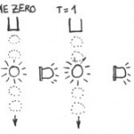
One of the important visual differences between something shot on video and something shot on film is the different depth-of-field (DOF). A film camera lens focuses onto an image of 35mm square (the size of the film frame), while a prosumer camcorder will focus to a much smaller 1/3" square (8.4mm) CCD element. This allows the film lens to exhibit a smaller DOF, which means that one can choose what to focus on. In contrast, a camcorder will have a larger DOF, so everything in the shot will be in focus.

The use of selective focusing is one of the hallmarks of current filmmaking (a bit overdone and a bit of a fad at the moment as well). And this selective focusing is an important aesthetic component and powerful artistic tool in the crafting of a visual story.

So how exactly can we make a camcorder exhibit a shorter DOF?

Simply screwing on a 35mm film camera lens will do no good, as the projection area of the CCD sensors has not changed. What we need to do is to be able to project the image from the 35mm lens onto an intermediate screen and then acquire the image from that projection into the camcorder.

Thus the 35mm DOF Adapter was created!

Published in: Artistica, Empirica | on January 31st, 2006 | No Comments »
Close
E-mail It